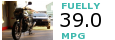
The 2 ignition coils are located on the frame towards the front near the fork, directly under the fuel tank and air box, just above the top of the engine. (Follow the spark plug wires up if you cannot find the coils.)
One is pictured here in the center of this picture. The other being located on the direct other side of the frame.
Though you can test the primary and secondary windings of the coils while they are attached to the bike, it is much easier with the front plastics removed, or even better the coil removed from the frame completely so that you may check for cracks in the housing or other physical damages. If you are taking them off, it would be a good idea to wire brush some of the rust off of the core if any is present around where the bolt holes are. Coating the bare metal with a clear lacquer, like clear nail polish for example, that little brush comes in handy!
The primary windings are the side of the coil that receives the initial electricity via two small gauged wires from the wire harness, the prongs are located on the front of the coil. The secondary windings are on the rear with the plug wires attached to them. See the pictures below for the prongs and wires.
Primary winding prongs with wires detached.
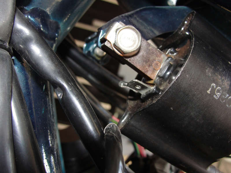
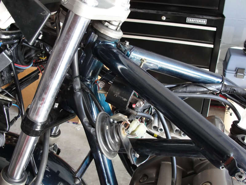
Secondary winding side via spark plug wires with one plug boot removed.
Once you have both plug boots unscrewed and removed you can put the tips of a multimeter into them (carefully.) Be sure the probes are touching the metal wires you will see at the end of the wire. Try to keep them placed into the center of these on both sides. Keep in mind only one coil can be tested at a time, so if you are testing the coils while they are on the bike remember that, Coil 1 controls cylinder 1 and 4. Coil 2 controls cylinder 2 and 3. Make sure you have a matching pair of plug wires.
Primary Testing
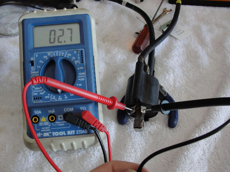
Notice the reading of 2.7ohm (not K ohm) This is ideal. A reading between 1.92ohm to 2.88ohm at 68degrees F is acceptable.
Secondary Testing
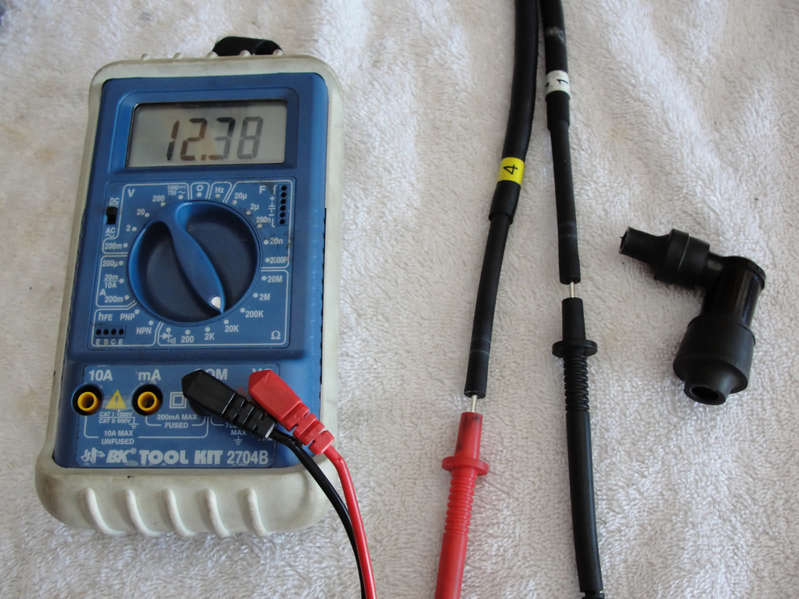
My coil is showing 12.38k ohm. Notice I am now in the K range, meaning x 1000 for measuring higher resistances. Be sure to check your multimeter for the proper setting when checking these. You won't hurt the coils or yourself if you're on the wrong setting, don't worry. A reading between 9520ohm (9.53k ohm) to 14,280ohm (14.28k ohm) at 68 F is acceptable.
If your coils are hotter than 68F or colder you will see different readings. Keep this in mind when testing.
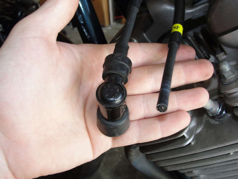
Plug Boot Testing
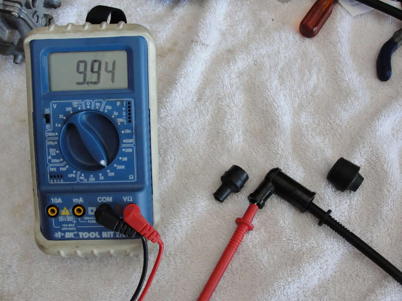
With the rubber ends removed (and cleaned) touch the two metal contacts at both ends. Your readings should be 10,000ohm (10k ohm). Specs do not specify any range but if you test all 4 and 1 is significantly different and no where near 10k it may be time for a replacement.
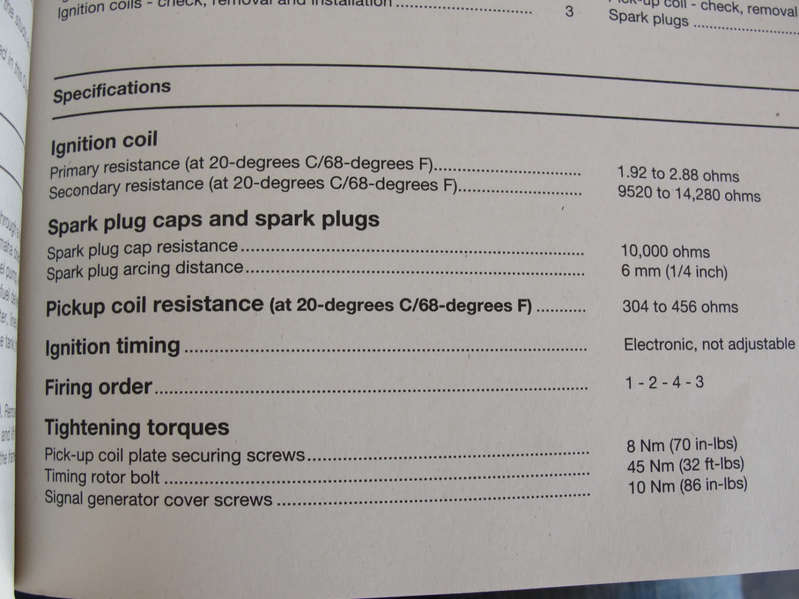
Here is what the book says for Specifications
If you have any readings out of range replace the coil or plug boot cap.