

The tools required:
6mm hex (allen) wrench or socket
4mm hex (allen) wrench or socket (socket preferably)
10mm wrench or socket & compatible rachet (to remove pinch bolt on shift shaft)
8mm socket and compatible rachet
1/2" drive rachet
1/2" drive torque wrench capable of 59 ft.-lb.
1/2" drive 14mm socket
1/2" drive 19mm socket
pliers
Flywheel holder or strap wrench
blue threadlocker
a small torque wrench if you want to properly torque the sprocket cover bolts (10 Nm), stator cover bolts (10 Nm), and shifter pivot bolt (30 Nm / 22 ft.-lb.).
The parts required:
Flywheel/magneto puller: Yamaha p/n 90890-01080 or Motion Pro p/n 08-0027 or a bolt M16 x 1.5 x 50mm (hard to find size)
Yamaha oil seal p/n 93102-25253
Optional: replacement o-ring for oil seal housing, Yamaha p/n 93210-45578-00
The starting point.

DISASSEMBLY:
Disconnect the negative battery lead.
Remove the bolt holding the shift lever assembly to the rearset using a 6mm hex wrench or socket

Remove the pinch bolt holding the shift lever assembly to the shift shaft. I believe my original bolt required a 10mm wrench or socket to remove, but I previously upgraded to a "socket head cap screw" which uses a hex key to remove. (if you wish to upgrade this pinch bolt it is an M6 x 1.0 x 20mm )
*Note the position of the shift assembly on the shift shaft. There is a small indentation on the end of the shaft which lines up with the opening of the shift assembly held together by the pinch bolt (the arrow in the picture below does not point the indentation)

Remove the sprocket cover using an 8mm socket and rachet. Some bolts for the sprocket cover are short, some are long. One of the long (65mm) bolts, on the right side of the cover going through the chain, has a spacer (mine doesn't at the moment, it was severely damaged when I had a chain failure (stretched-out), and I haven't gotten around to replacing it yet). The picture below shows the location of the bolts i pulled out of my sprocket cover and where they were located.

Remove the stator cover using an 8mm socket and rachet. The picture below shows that I already removed the bottom bolt from the stator cover. The stator is attached to the inside of the cover. The rotor, which is bolted onto the shaft, is a magnet, so when removing the stator cover after the cover bolts are removed, simply pull hard towards you to fight the magnetic force. The stator can remain plugged in and the stator cover with stator attached can simply be set on the ground under the rearset area of the bike.

The picture below shows the rotor bolt which must be removed to remove the rotor to access the oil seal.

Removing the rotor bolt requires a 14mm socket and a flywheel holder (possible clearance issues) or a strap wrench (possible clearance issues). The frame got in the way of using the strap wrench properly, but worked just well enough to allow removal of the rotor bolt.

Here is a side-by-side of the rotor bolt and the flywheel/rotor puller (Motion Pro)

Remove the rotor by threading the flywheel/rotor puller into the hole the rotor bolt came from. Hold the rotor in place using your strap wrench while tightening the flywheel/rotor puller (righty-tighty) using 19mm socket (for the Motion Pro puller) until the rotor backs off the shaft. It took very few turns before the rotor popped off. Set the rotor on a clean surface that will not allow metal bits (shavings, washers, etc.) to stick to it.

Here is a picture of what is behind the rotor. Remove the screws and bracket using a 4mm hex socket (you can use an "L" shaped hex key, but these screws are in tight and removing them with an "L" shaped hex key versus a hex socket could snap the hex key). Note the way the bracket holds the oil seal housing in place (arrows in picture)

Here is a picture after the bracket has been removed. You can see the oil seal (brown) and an oil nozzle that was partially obscured by the bracket.

SPOILER ALERT (edited 8-22-2-12): After I replaced the oil seal and put everything back together, the leak remained. I now believe the culprit could be the oil nozzle seen in the picture above. The nozzle (Yamaha p/n 4BR-15148-00-00) has an o-ring (Yamaha p/n 93210-11453-00) on it, but I did not attempt to remove the nozzle for fear that there was a rollpin holding it in place on the inside of the engine. After doing research, I've discovered there is not a rollpin holding it in place. I ordered a replacement o-ring (will post the dimensions once it arrives), the next time I have the stator and rotor off, I will use needle-nose pliers to remove the oil nozzle to inspect it and it's o-ring for failure. I recommend replacing this o-ring while you are in there. Here is a picture i found online of the oil nozzle in question.
Remove the housing in which the oil seal sits by using pliers to gently pull towards you at the points seen in the picture below

Do Not attempt to remove the housing by prying it out using a screwdriver, as pictured below, as it could scratch the engine casing and lead to further oil leaks

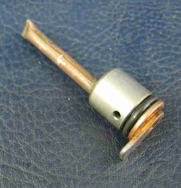
Remove the housing with the oil seal

Side view of the housing (to show o-ring)

View of the shaft bearing

Push the old oil seal out of the housing, should be in there tight. (you can see where i removed the housing o-ring to inspect it's condition).

REASSEMBLY:
Press your new oil seal into the housing, review the pics above for orientation of the oil seal.
Be sure the large o-ring is in it's grove on the oil seal's housing and push the housing back into position, but be sure to have the housing installed in such a way as to allow the bracket to hold it in place. this is shown in the picture below

Although I could not find it expressed in any literature, you may wish to apply a tiny bit of blue threadlocker to the bracket screws before installing the bracket since it could cause significant damage to the rotor if one of those screws were to work it's way loose.
Inspect the rotor for metal bits and remove if any are found (it's a magnet)
Place the rotor back on the shaft giving it a few gentle taps to partially seat it.
Apply blue threadlocker to the rotor bolt.
Torque the rotor bolt to 59 ft.-lb. using a 14mm socket while holding the rotor in place using a flywheel holder or strap wrench. This is the most difficult step, in my opinion, due to the rotor fighting the strap wrench which I was already having a difficult time holding properly. I ended up breaking my strap wrench on this step.
Replace the stator cover with stator attached. Install the three bolts using an 8mm socket.
Replace the sprocket cover. Be sure the plastic spacer is on the shift shaft (it can be seen in the pics where arrows are pointing to the stator cover bolts and rotor bolt). Install the six bolts using an 8mm socket (note: some bolts are short and some are long, as i pointed out upon disassembly, and the long one on the middle-right should have a spacer since it goes between the chain)
Replace the shift assembly onto the shift shaft being sure to align the indentation on the end of the shift shaft as shown in the disassembly step at the beginning of this tutorial.
Install the shift assembly pinch bolt.
Apply blue threadlocker to the shift assembly pivot bolt. Be sure there is a washer (one with a large ID, one with a small ID) on either side of the shift lever where the bolt goes through. Install the bolt using a 6mm hex socket or wrench. (If so desired, torque to 22 ft.-lb. or just "nice and tight")
Reconnect negative battery lead to the battery.
Done.